spibuttonlib
| Crates.io | spibuttonlib |
| lib.rs | spibuttonlib |
| version | 0.1.0 |
| created_at | 2026-01-02 16:19:48.407632+00 |
| updated_at | 2026-01-02 16:19:48.407632+00 |
| description | SPI button library for lamp-buttons with MC14021B and MC14094B or equivilant shift registers. |
| homepage | |
| repository | https://github.com/kpishere/spibuttonlib.git |
| max_upload_size | |
| id | 2018846 |
| size | 48,383 |
 (kpishere)
documentation
README
SPI Buttons Rust Implementation
This is a Rust re-implementation of the spi_buttons repository, tested on Beaglebone Black, using the Linux SPI device interface.
Overview
The original project controls buttons with lights using SPI shift registers with MC14021B and MC14094B or equivalent shift registers. This version implements the same logic in Rust, using the spidev library for SPI communication via the Linux SPI device driver.
SPI Implementation
The implementation uses the Linux spidev interface to communicate with SPI shift registers. The SPI peripheral handles the low-level pin toggling for SCK (clock), MOSI (data out), MISO (data in), and CS (chip select).
Pin Usage Diagram
Beaglebone Black Pinout (SPI via spidev)

P8 Header:

P9 Header:
  31: SPI1_SCLK (SCK)     - Serial Clock (SPI clock signal)
  29: SPI1_D0 (MISO)      - Master In Slave Out (data from shift registers)
  30: SPI1_D1 (MOSI)      - Master Out Slave In (data to shift registers)
  28: SPI1_CS0 (CS)       - Chip Select (enables SPI communication)

Shift Register Connections:
- Serial Data In  <- MOSI (P9_30)
- Serial Clock    <- SCK (P9_31)
- Serial Data Out -> MISO (P9_29)
- Chip Select     <- CS (P9_28)
SPI Pins Description
- MOSI (P9_30, SPI1_D1): Outputs serial data to the shift registers' data input.
- SCK (P9_31, SPI1_SCLK): Provides the clock signal for synchronizing data transfer.
- MISO (P9_29, SPI1_D0): Reads serial data from the shift registers' data output.
- CS (P9_28, SPI1_CS0): Chip select signal to enable/disable SPI communication.
GPIO Access
Dependencies
spidev: For SPI communication via the Linux SPI device interface.
Building
The PRU firmware is no longer used; SPI communication is handled by the Linux SPI driver.
To build the project:
cargo build
Testing
Run the unit tests to verify the button logic:
cargo test
Running
- Build the Rust program:
cargo build
The program uses the SPI device at /dev/spidev1.0.
========
SPI Buttons
This came from a weekender project to make a utility class for controlling some buttons with lights because well, there is just a little too much touch screen in the world today and such physical interfaces are becoming a little bit special -- and appreciated.
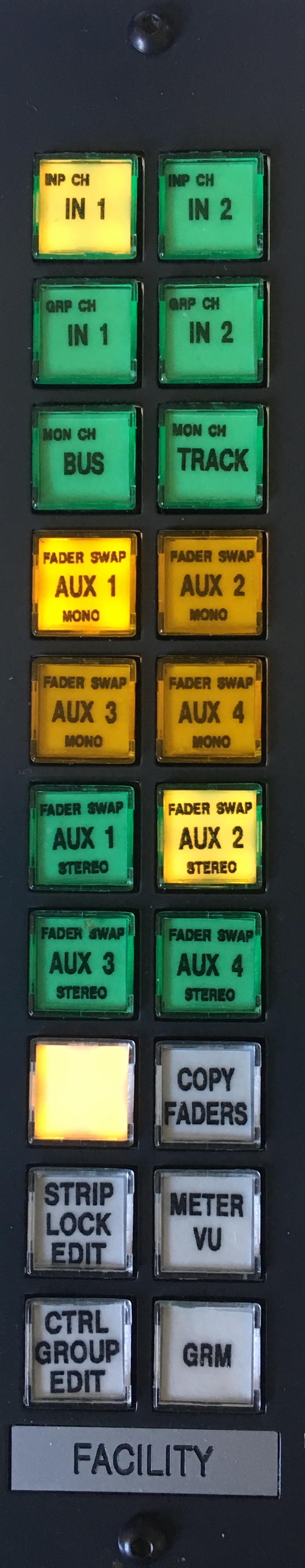
The driver and test rig for this project is what you see below. A button panel from a salvaged video broadcast control unit of some sort (do you recognize this for the equipment from which it comes?).
The buttons have clear-cap pop-offs where you can put laser/jet printed text on mylar film under them and have backlit lamps.
The lamps in this case consume quite a bit of power (64mA each which totals about 1A when all are lit).
Feature wise, the class provides callback to your code for press down, press up, and hold events. There is option to have class do the toggle on/off if that is all you need and get the callback on that event. There are four button states : On, Off, Flash 1, and Flash 2. Flash 2 is faster flashing than Flash 1. The buttons are animated for positive feedback - you press them and the light inverts from off/on and visa versa.
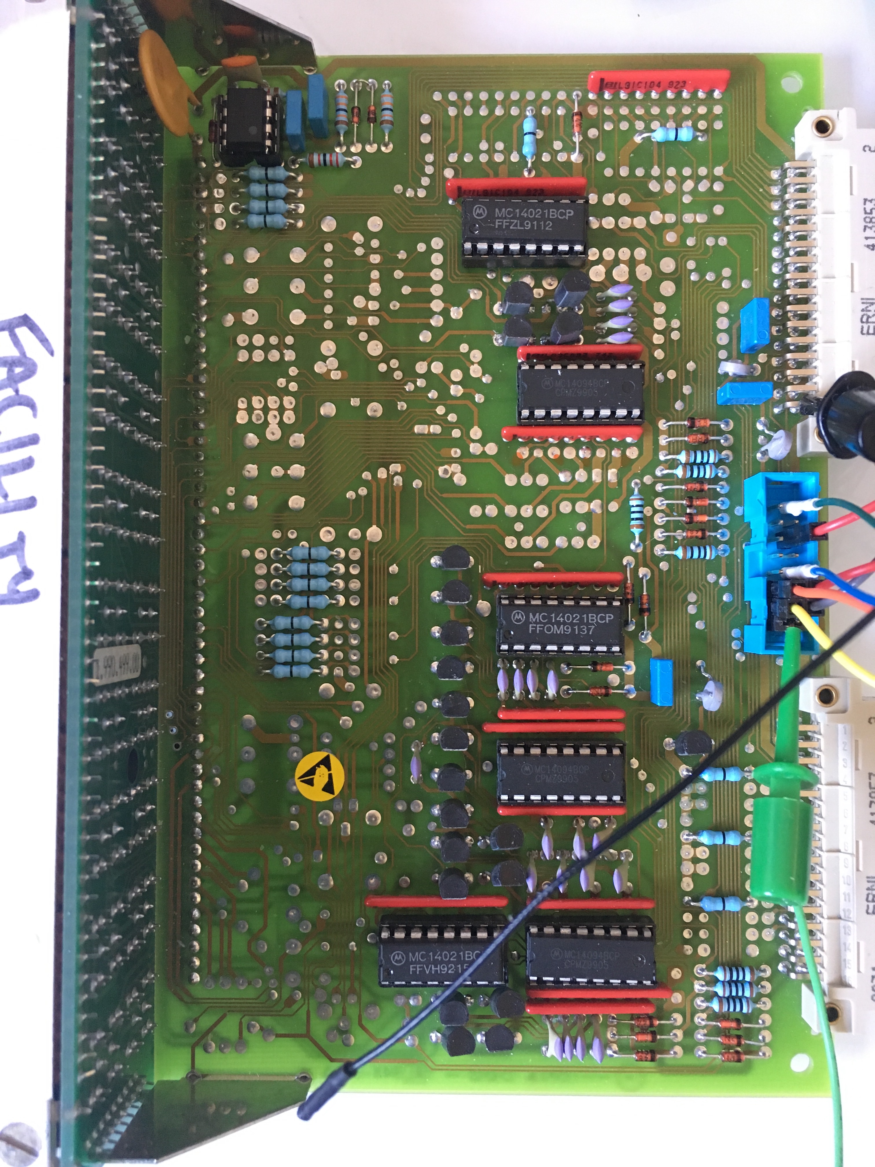
[Don't ask me why that op-amp is in the upper left corner of board, I don't know. It isn't used. I'd noted that it's output is linked to a driver transistor for about 300mA capacity output.]
For this specific board, the wiring on the blue connector is :
CLK - Pin 52 - Button+Lamp Clock - Header pins 15,16 CS - Pin 53 - Button P/S - Header pin 14,11,9 MOSI - Pin 51 - Lamp - Header pin 13 MISO - Pin 50 - Button - Header pin 12
GND - Header pin 2,4 VDD - Header pin 5 - 3.3V or 5V PWR - Header pin 6 - Lamps 5V (320ma max)
| Face | Board |
|---|---|
 |
 |