voronoi_mosaic
| Crates.io | voronoi_mosaic |
| lib.rs | voronoi_mosaic |
| version | 0.5.0 |
| created_at | 2025-08-09 16:47:48.214011+00 |
| updated_at | 2025-10-06 11:51:11.822914+00 |
| description | Bevy mesh generation from Delaunay Triangulation and Voronoi Tessellation |
| homepage | https://github.com/BlondeBurrito/voronoi_mosaic |
| repository | https://github.com/BlondeBurrito/voronoi_mosaic |
| max_upload_size | |
| id | 1788069 |
| size | 383,935 |
 (BlondeBurrito)
documentation
README

![]()
![]()


voronoi_mosaic
Bevy mesh generation from a series of points in space using Delaunay Triangulation and Voronoi Tessellation.
| bevy | voronoi_mosaic |
|---|---|
| 0.17 | 0.5 |
| 0.16 | 0.1 - 0.4 |
Table of Contents
Intro
This library is designed to generate Bevy meshes from a series of points in space.
Delaunay Triangulation
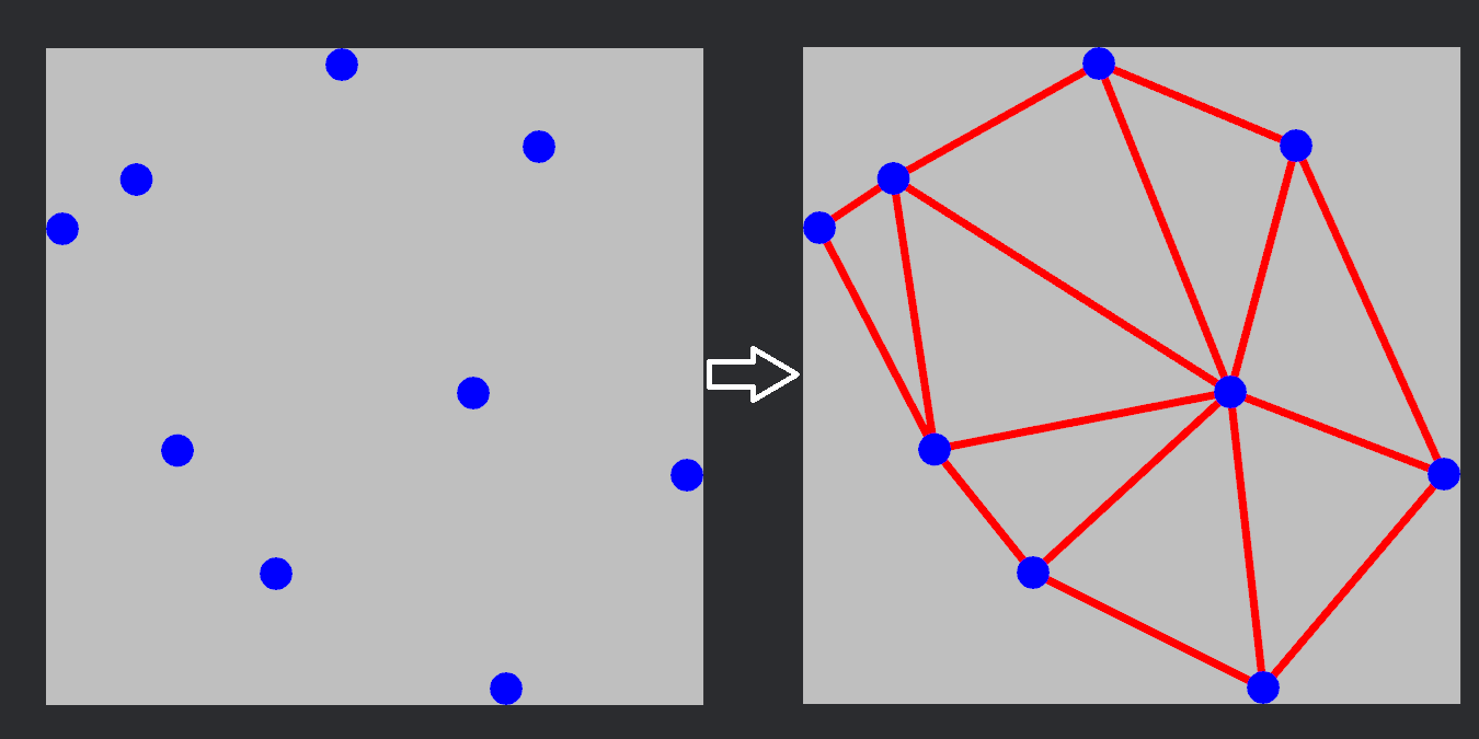
Delaunay Triangulation describes a set of data points in space that form a series of triangles whereby each circumcircle of a triangle does not contain any of the data points.
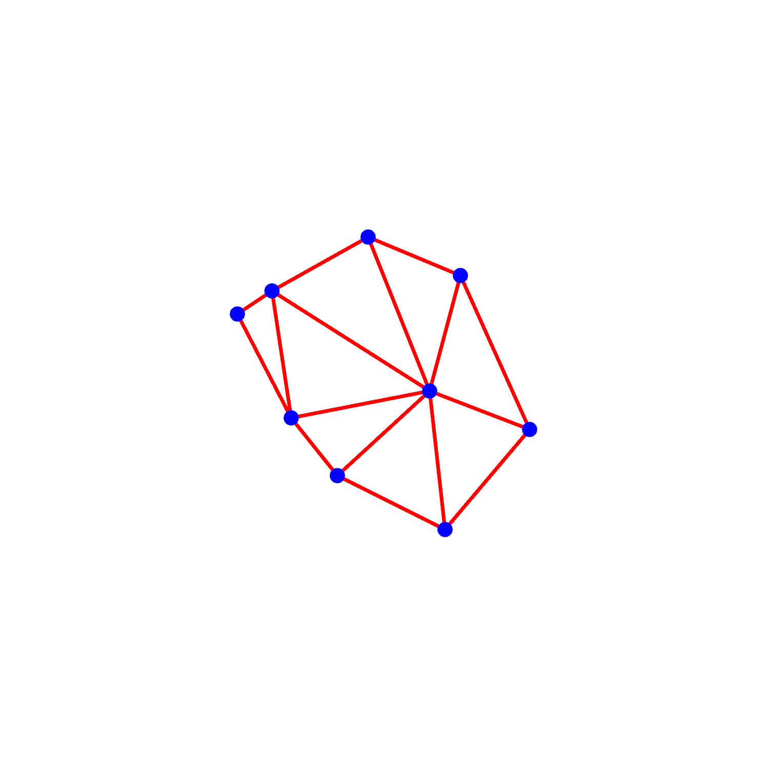
A series of data points that have been triangulated:
When dealing with 3d we migrate to Delaunay Tetrahedralization and the set of data points form tetrahedra with the condition that no data point sits inside a circumsphere of a tetrahedron.
Process
2d
To read through the triangulation process click to exapnd
Triangulation involes generating a series of triangles and recording good and bad triangles. A bad triangle fails to meet the properties of a Delaunay triangle, i.e its circumcircle contains a data point. A valid Delaunay triangle should not contain any data points.
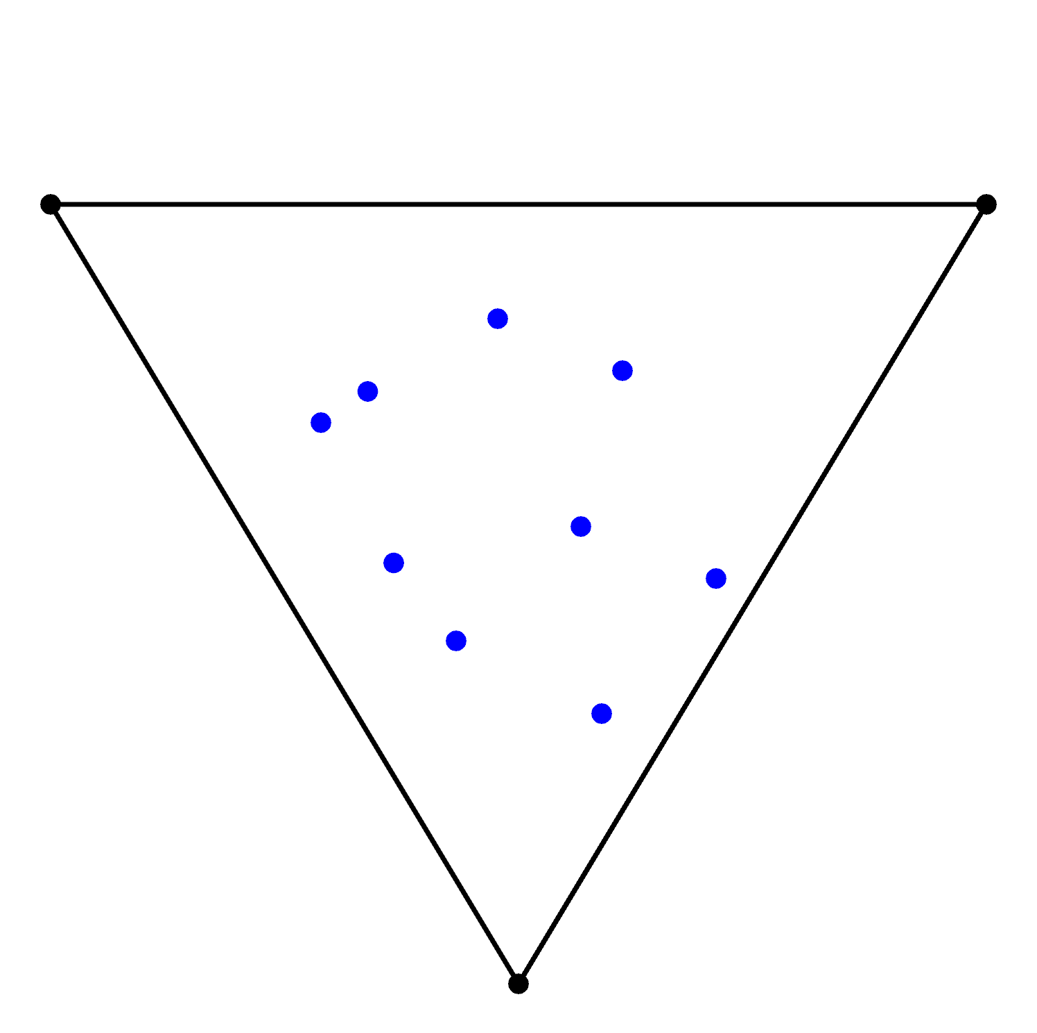
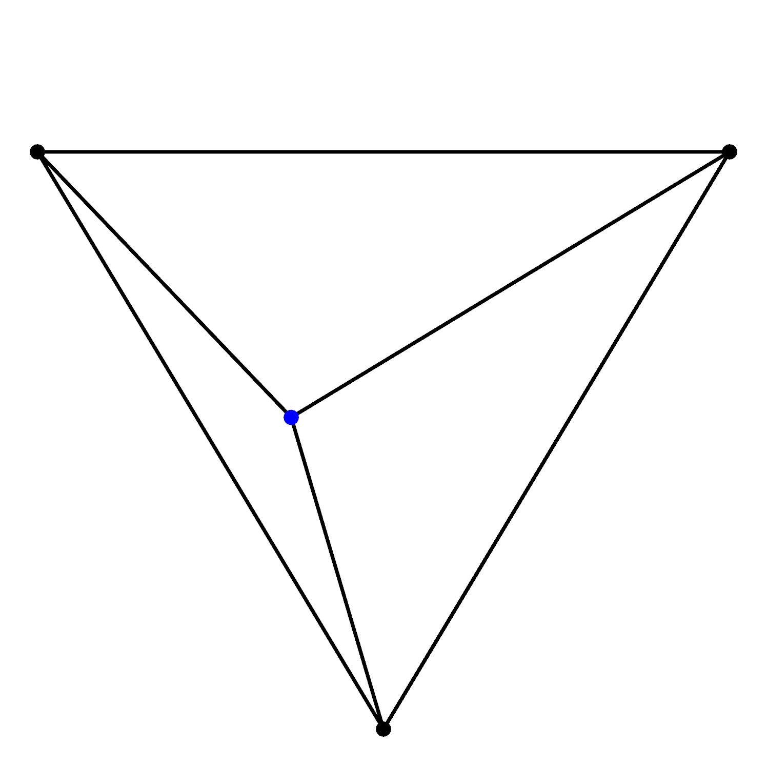
We begin with a set of data points (blue) and we enclose them in a super triangle (black):
NB: super triangle needs to enclose the all possible circumcircles between data points for the triangulation to be accurate. The diagrams show a smaller than normal super triangle for illustrative purposes
Beginning with just one of the data points we calculate the circumcircle (orange) of the known triangle:
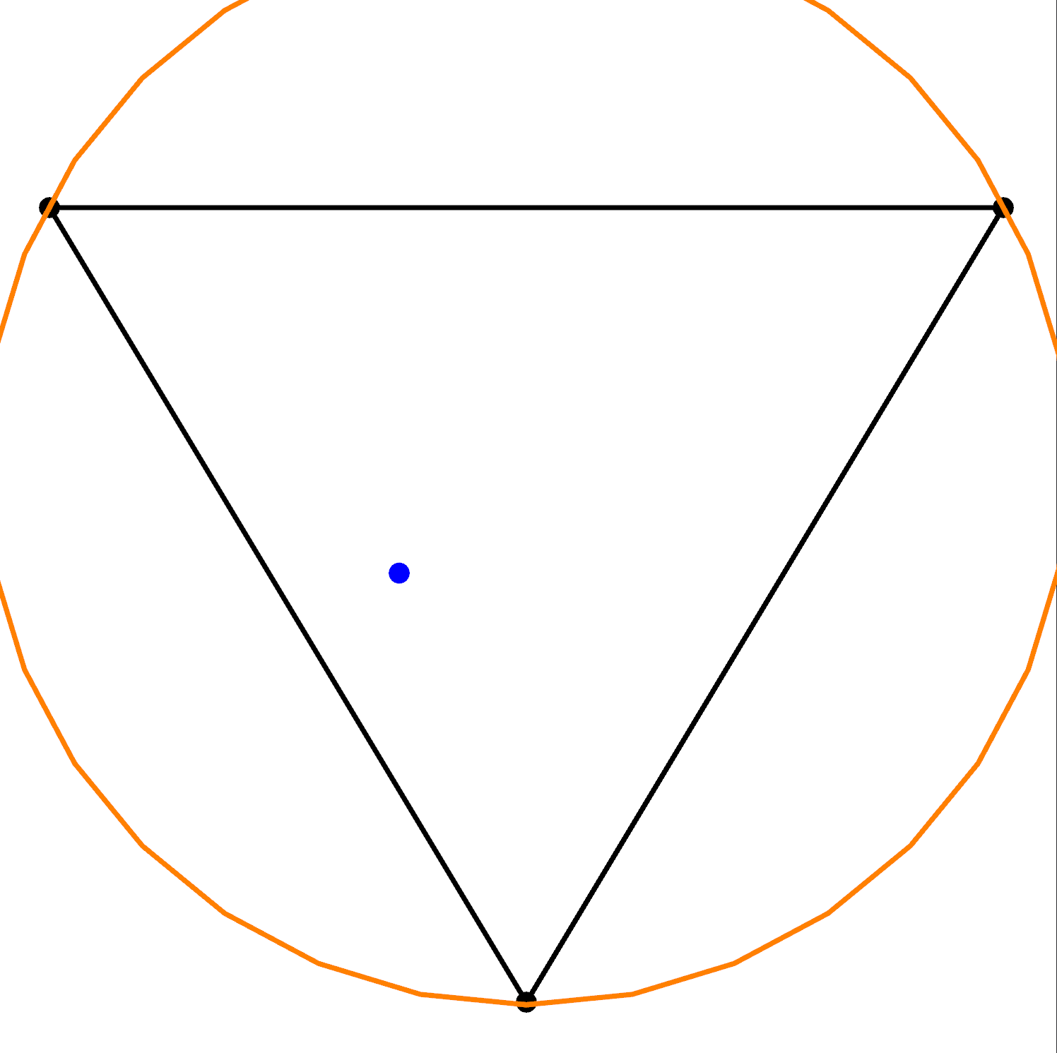
As you can see the data point lies within the circumcircle so we know this triangle isn't Delaunay, we remove this bad triangle and use its vertices to contruct new triangles with the data point:
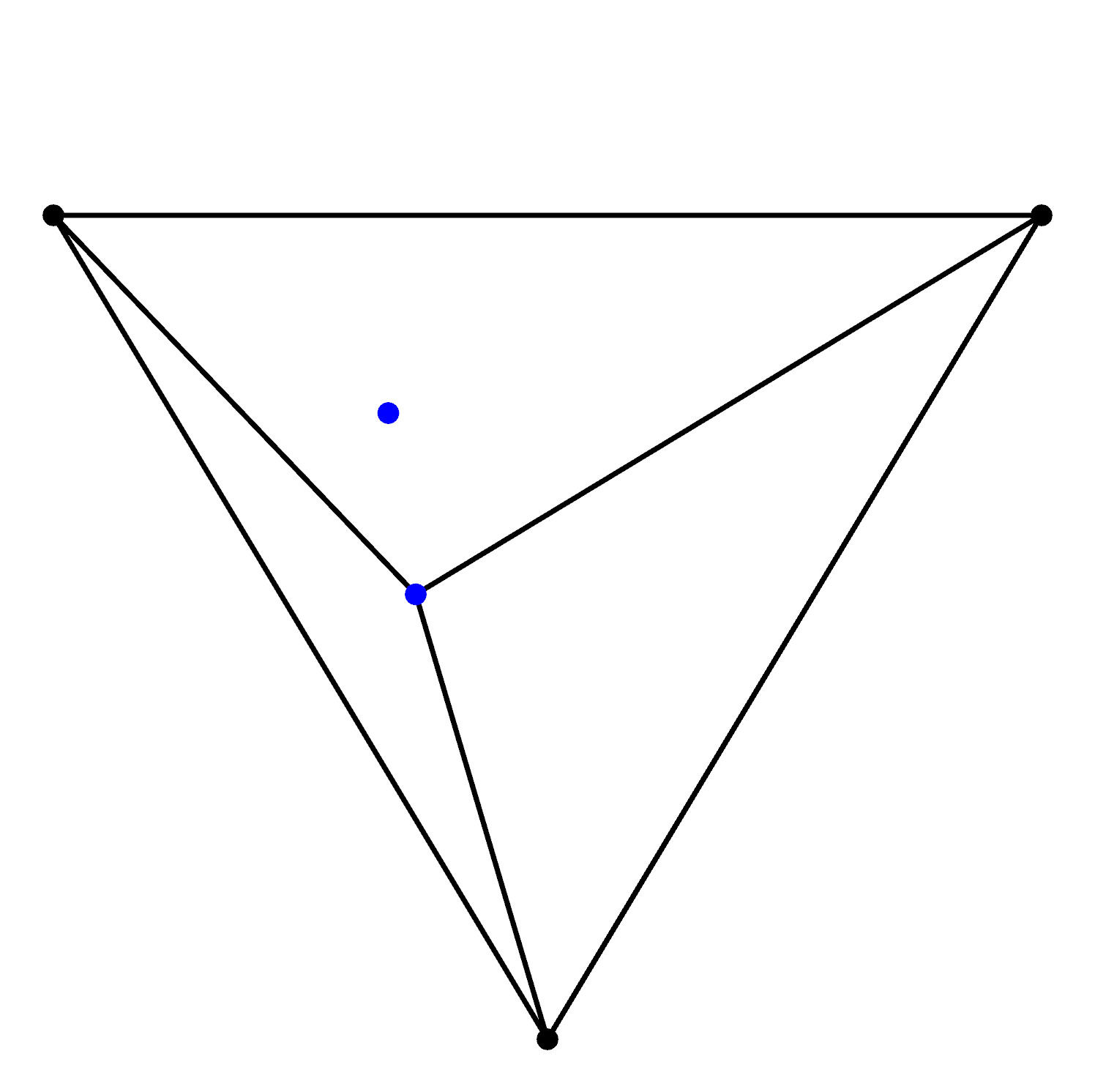
At this point in time we have three Delaunay triangles but we haven't processed all the data, now we add another data point:
And construct new circumcircles with the known triangles to see if any are Delaunay or not:
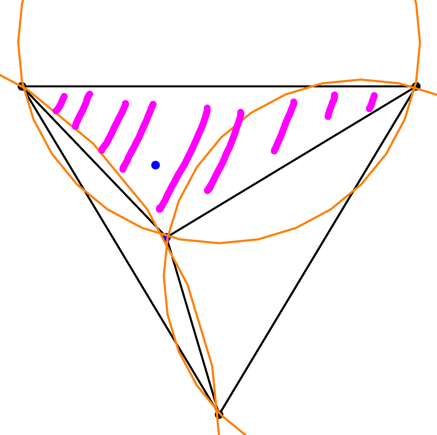
As can be seen, the new data point does lie within the circumcircle of one of the triangles, so again we have a bad trinagle (pink hash), we remove this triangle and using its vertices construct new triangles with the data point:
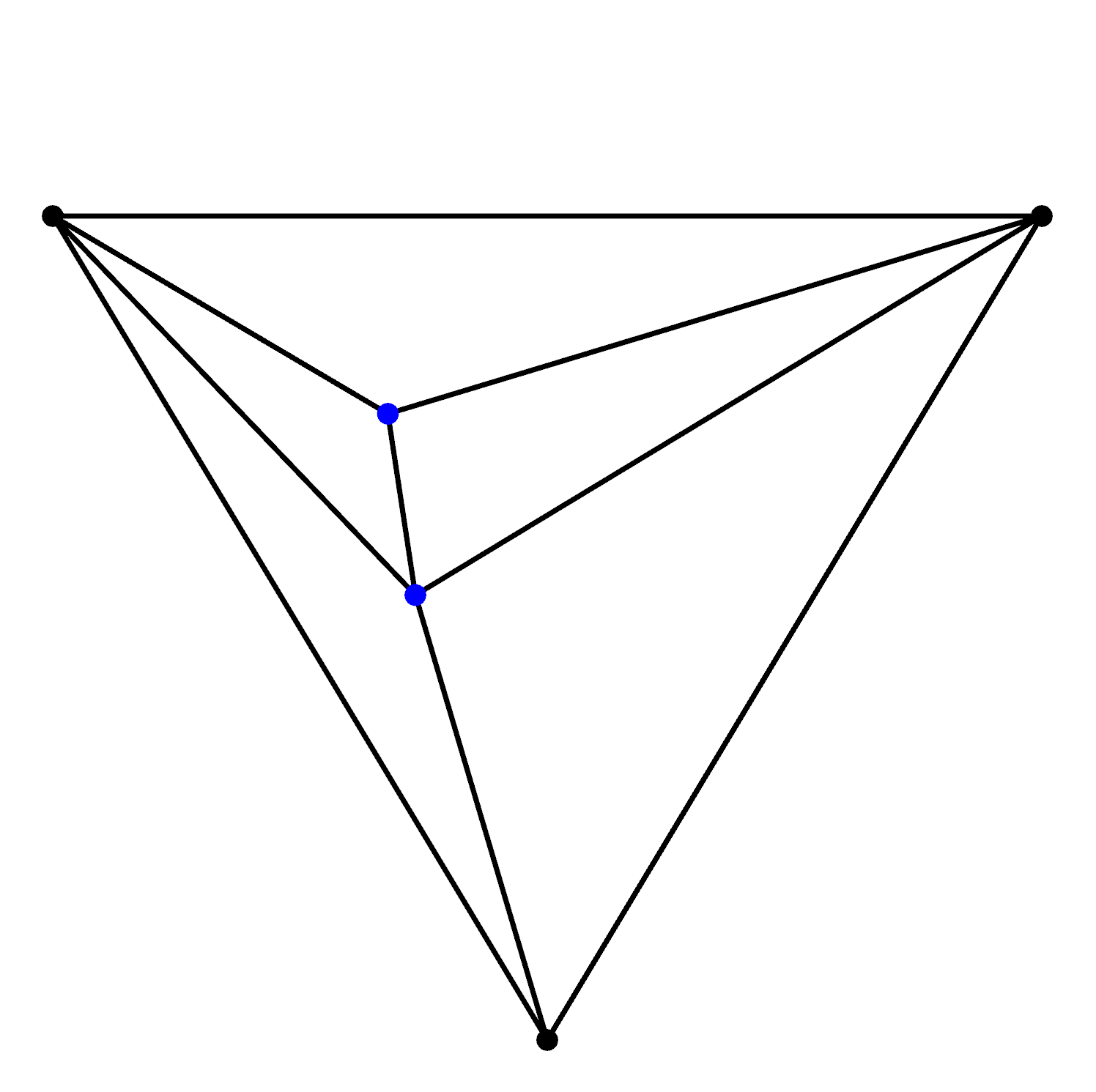
We then start the whole process over again of adding a new data point, computing circumcircles, removing bad triangles and so on.
Once all data points have been added we must then remove any triangles using the vertices of the initial super triangle as they are not part of the data set, merely a starting point of triangulation. The end result generates a collection of Delaunay triangles:
3d
To read through the tetrahedralization process click to exapnd
Triangulation in 3d is also known as tetrahedralization.
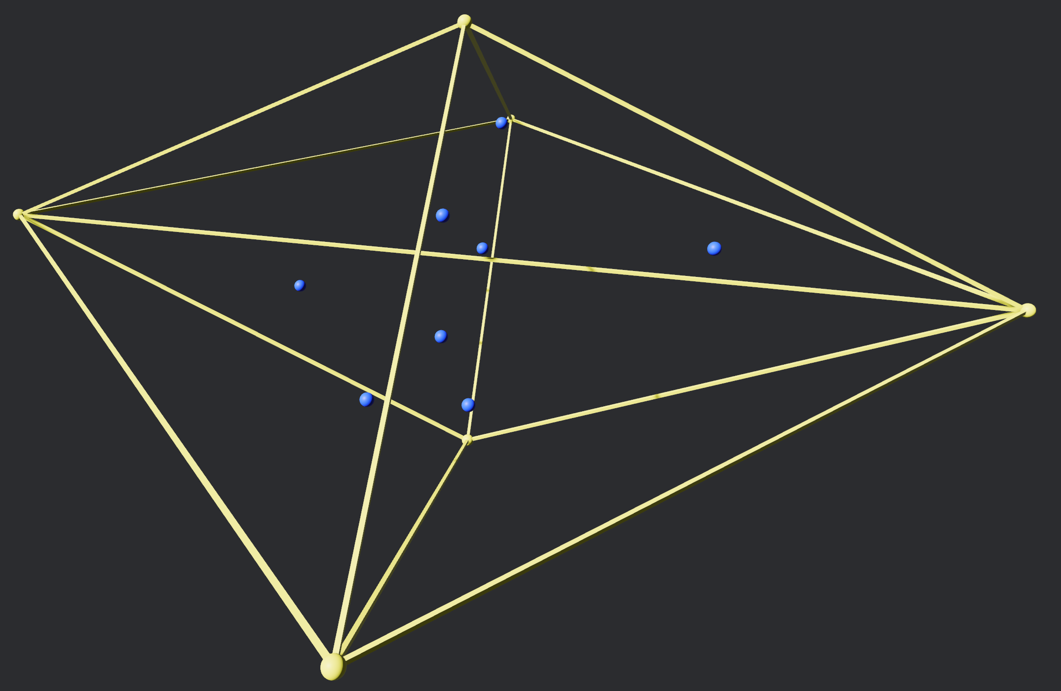
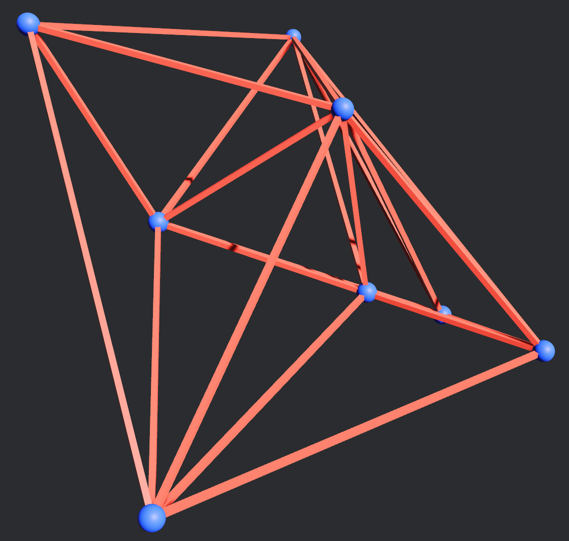
In a simialr fashtion to the 2d case we want to enclose all data points within a structure, rather than using a single tetrahedron we in fact use 4 tetrahedra (yellow) arranged in a diamond like configuration to ensure that all data points (blue) are enclosed and that any circumspheres between data points are also enclosed:
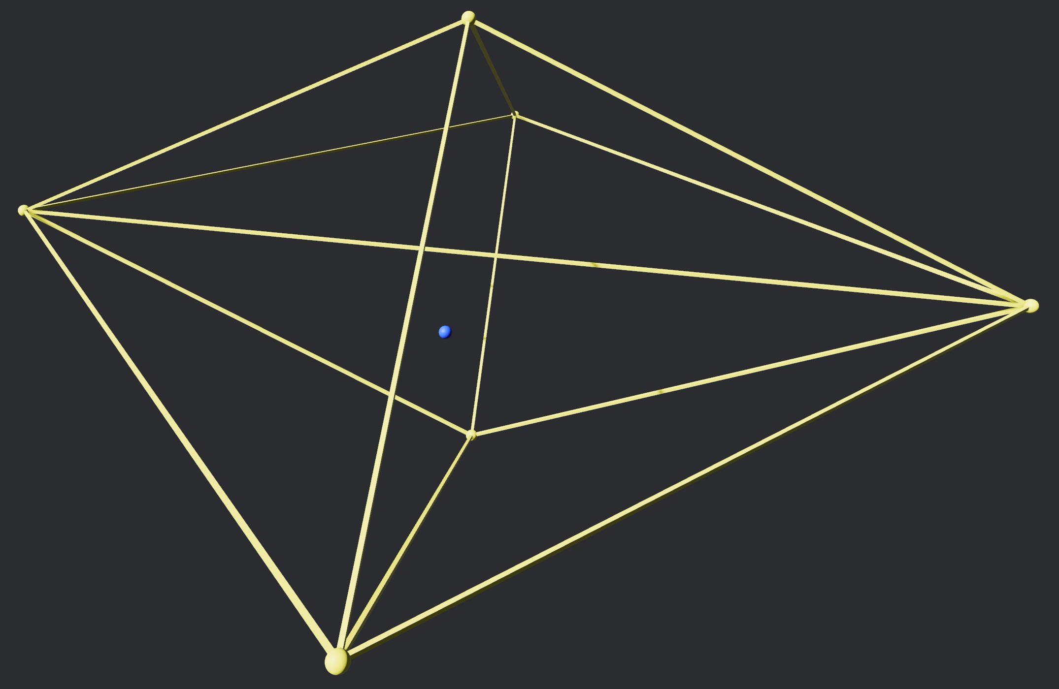
We then begin with just a single data point:
And we compute the circumsphere of each tetrahedron (we'll only show one here for visual clarity as a wireframe):
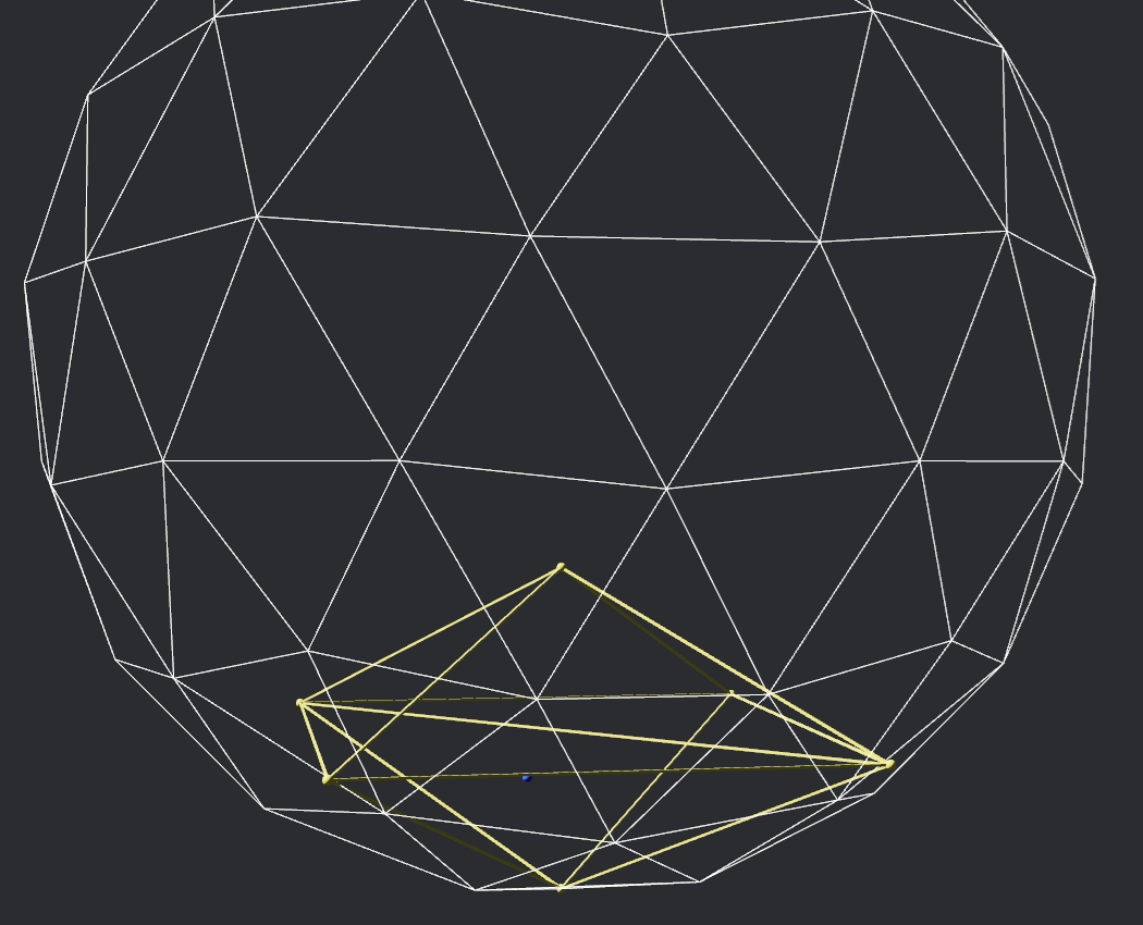
The point is evidently within the circumsphere so we note that its tetrahedron is bad and not Delaunay, so we remove it from the set of final tetrahedra leaving behind a polyhedral hole. We collect all the faces of the bad tetrahedra, identify unique faces (i.e a face that crosses the polyhedral hole is shared by two tetrahedra so we ignore it) and join them to the data point - this creates new tetrahedra that fill the hole. These can then be used to progress tetrahedralization.
We continue adding data points one at a time and using circumcspheres to identify any invalid tetraheda. Once all data points have been computed we tidy up by removing any tetrahedra that make use of any of the vertices of the original 4 bounding tetrahedra. This gives us the final tetrahedralization where each one is Delaunay:
TODO: replace this image now that 3d delaunay is fixed
Voronoi Tessellation
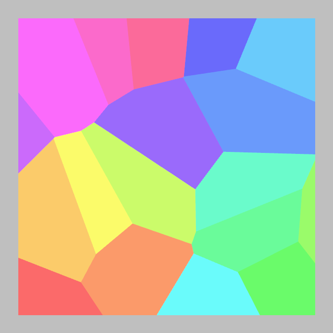
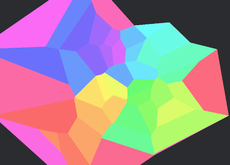
A Voronoi Tesselation (or Voronoi diagram) describes a number of regions (referred to here as Cells) for which all points in a plane belong to a particular Cell.
Here is an example showing each Cell as a different colour (some cells extend beyond the viewport):
Process
2d
For the details of converting Delanay Triangulation into Voronoi click to expand
Starting with a set of Delaunay traingles (red and blue) we can calculate the circumcentres of each (orange):
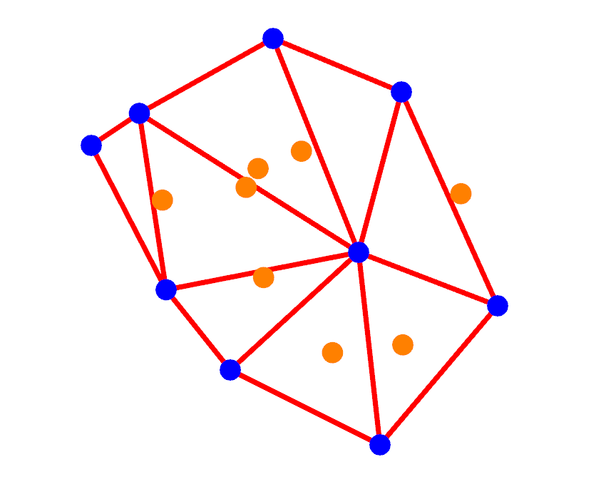
These circumcentres are the vertices of Voronoi Cells -we just need to figure out the edges joining these vertices together.
A property we can observe is Delaunay triangle vertex sharing - as in adjacent triangles share a pair of vertices which means that the circumcentres of those two triangles are an edge (pink) of a Cell:
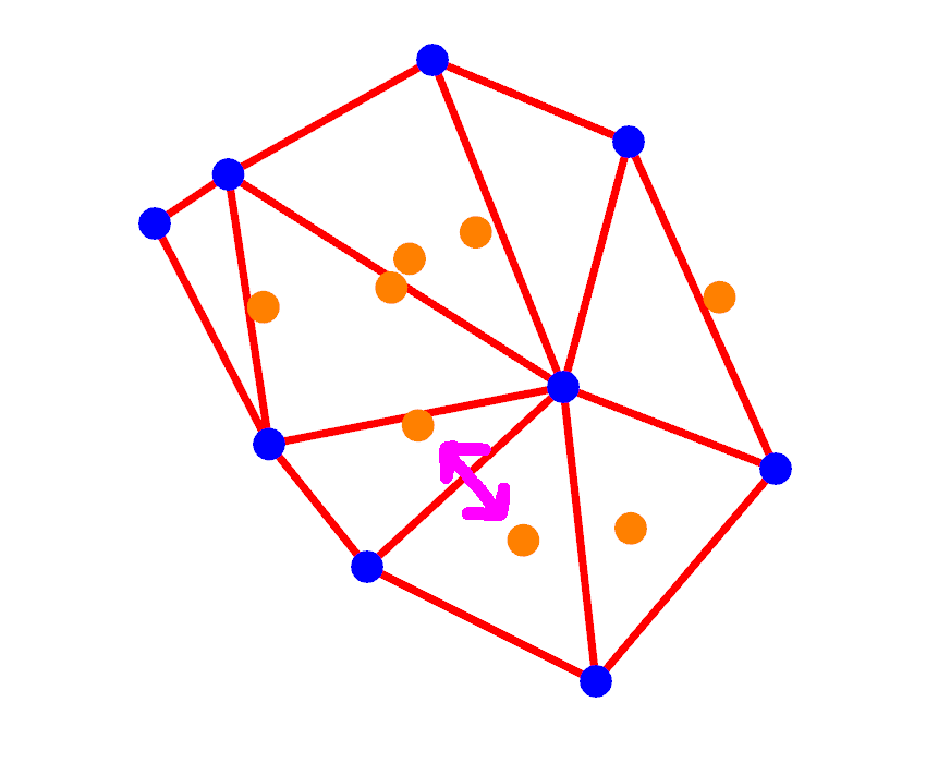
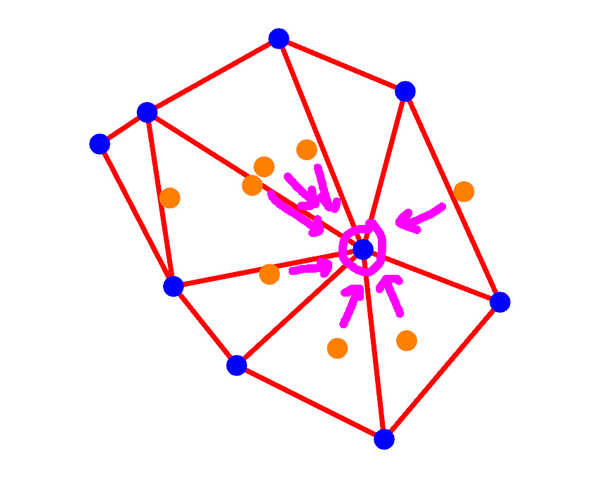
Additionally we can observe cases where a triangle vertex is shared more than two times with other triangles (in the code we call this source_vertex, it's the link bewteen Vornoi and Delaunay). For these points we know that the surrounding circumcentres are the vertices of this Cell:
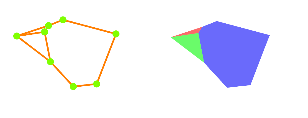
From these properties we can construct the Voronoi Cells, on the left is a illustrative outline, on the right a colour coded representation of the Cells:
3d
NB: parts of the 3d API are volatile or still under development
For the details of converting Delanay Tetrahedralization into Voronoi click to expand
WIP
Usage
2d
Update your Cargo.toml with
[dependencies]
voronoi_mosaic = { version = "x.y.z", features = ["2d"] }
Delaunay
Generating the Delaunay simply requires a series of points in space:
use bevy::prelude::*;
use voronoi_mosaic::prelude::*;

let points: Vec<Vec2> = vec![...];
if let Some(delaunay) = Delaunay2d::compute_triangulation_2d(&points) {
	// do something with the data
}
For a full visualisation you can check out this example 2d_delaunay.
Voronoi
With some generated Delaunay data the Voronoi Cells can easily be generated:
use bevy::prelude::*;
use voronoi_mosaic::prelude::*;

let points = vec![...];
if let Some(delaunay) = Delaunay2d::compute_triangulation_2d(&points) {
	if let Some(voronoi) = Voronoi2d::from_delaunay_2d(&delaunay) {
		// do something with the generated cells
	}
}
For a full visualisation you can check out this example 2d_voronoi.
Meshes
The Voronoi data can be converted into Bevy meshes like so:
use bevy::prelude::*;
use voronoi_mosaic::prelude::*;

let points = vec![...];
if let Some(delaunay) = Delaunay2d::compute_triangulation_2d(&points) {
	if let Some(voronoi) = Voronoi2d::from_delaunay_2d(&delaunay) {
		// convert the cell data structures into bevy meshes
		let meshes = voronoi.as_bevy2d_meshes();
	}
}
For a full visualisation you can check out this example 2d_meshes.
Clipping
Voronoi Cells can be clipped to a boundary - this means that any Cells outside of a given boundary are dropped and any that overlap the boundary have their vertices clipped to the boundary edge.
It is important to note that clipping involves adding/removing vertices, this shatters the duality between Voronoi and Delaunay - once clipped you wouldn't be able to convert Voronoi to Delaunay and expect to get your original data set back.
use bevy::prelude::*;
use voronoi_mosaic::prelude::*;

let points = vec![...];
if let Some(delaunay) = Delaunay2d::compute_triangulation_2d(&points) {
	if let Some(voronoi) = Voronoi2d::from_delaunay_2d(&delaunay) {
		// define a series of boundary vertices that form a polygon
		// they must be in anti-clockwise order!
		let boundary = vec![...];
		// generate meshes clipped to the boundary
		let meshes = voronoi.as_clipped_bevy2d_meshes();
	}
}
For a full visualisation you can check out this exmaple 2d_meshes_clipped. It has a button toggle to show the original Voronoi cells so you can see how they are clipped to the boundary.
3d
NB: parts of the 3d API are volatile or still under development
NB: a concept of tolerance is built into some of the 3d calculations to handle cases where points within a data set are close together, however, if points within the data set are extremely close together then due to floating point arithmetic the conditions for a tetrahedron to be Delaunay can break down and cause undesirable face intersections across sliver (narrow) tetrahedra
Update your Cargo.toml with
[dependencies]
voronoi_mosaic = { version = "x.y.z", features = ["3d"] }
3d usage minimised until API work complete, the enclosed functions are subject to change and some may not fucntion as expected yet
Delaunay
Generating the Delaunay simply requires a series of points in space:
use bevy::prelude::*;
use voronoi_mosaic::prelude::*;

let points: Vec<Vec3> = vec![...];
if let Some(delaunay) = Delaunay3d::compute_triangulation_3d(&points) {
	// do something with the data
}
For a full visualisation you can check out this example 3d_delaunay.
Voronoi
With some generated Delaunay data the Voronoi Cells can easily be generated:
use bevy::prelude::*;
use voronoi_mosaic::prelude::*;

let points = vec![...];
if let Some(delaunay) = Delaunay3d::compute_triangulation_3d(&points) {
	if let Some(voronoi) = Voronoi3d::from_delaunay_3d(&delaunay) {
		// do something with the generated cells
	}
}
For a full visualisation you can check out this example 3d_voronoi.
Meshes
NB: still in development
The Voronoi data can be converted into Bevy meshes like so:
use bevy::prelude::*;
use voronoi_mosaic::prelude::*;

let points = vec![...];
if let Some(delaunay) = Delaunay3d::compute_triangulation_3d(&points) {
	if let Some(voronoi) = Voronoi3d::from_delaunay_3d(&delaunay) {
		// convert the cell data structures into bevy meshes
		let meshes = voronoi.as_bevy3d_meshes();
	}
}
For a full visualisation you can check out this example 3d_meshes.
Clipping
NB: still in development
Voronoi Cells can be clipped to a boundary - this means that any Cells outside of a given boundary are dropped and any that overlap the boundary have their vertices clipped to the boundary edge.
It is important to note that clipping involves adding/removing vertices, this shatters the duality between Voronoi and Delaunay - once clipped you wouldn't be able to convert Voronoi to Delaunay and expect to get your original data set back.
use bevy::prelude::*;
use voronoi_mosaic::prelude::*;

let points = vec![...];
if let Some(delaunay) = Delaunay3d::compute_triangulation_3d(&points) {
	if let Some(mut voronoi) = Voronoi3d::from_delaunay_3d(&delaunay) {
		// define a series of boundary vertices that form a polygon
		// they must be in anti-clockwise order!
		let boundary = vec![...];
		// do something with the clipped cells like turning them into meshes
		let meshes = voronoi.as_clipped_bevy3d_meshes(&boundary);
	}
}
For a full visualisation you can check out this exmaple 3d_meshes_clipped.
Performance
A number of benchmarks are included to measure the different phases of calculation.
You can run all benchmarks with:
cargo bench -q --benches --workspace --all-features
Or target a benchmark specifically:
cargo bench -q --bench BENCH_NAME --workspace --all-features
Once executed a browser based report can be viewed at [your_repo_root]/target/criterion/report/index.html
LICENSE
Dual license of MIT and Apache.
Possible future work
- Given floating-point arithmetic is used consider introducing some kind of tolerance measure, e.g for testing vertex presence within a polygon, handling a point very close to the surface of a circumspehre or edge of a circle
- Consider special handling of extremely acute triangles, disposing of sliver triangles in certian cases?
- Degenerate triangle detection?
- Add a means of testing DT for determinism
- how to measure tetrahedron quality? Sterdian angles? Volume?
- make edge and triangle modules generic across Vec2 and Vec3?
- benches, use step_by()